Shaping hard and brittle materials, e.g. cermets, at micrometer resolution has long been known challenging for both mechanical machining and high energy beam based additive manufacturing. Digital light processing (DLP), which features great printing quality and decent precision, unfortunately lacks capability to deal with the popular slurry-typed cermet precursor due to the tremendous optical absorption by its particles. Here, an innovative protocol based on a versatile collapsable matrix is devised to allow high-precision printing of WC-Co cermets on DLP platform. By tuning the external environment, this matrix attenuates composite powders to facilitate photopolymerization at the printing stage, and shrinks to condense green parts prior to thermal sintering. The as-obtained samples by collapsable matrix assisted DLP can reach a relative density of ≈90%, a record-breaking resolution of ≈10 µm, and a microhardness of up to 14.5 GPa. Complex delicate structures, including school emblem, honeycomb, and micro-drill can be directly fabricated, which has never been achieved before. Impressively, the as-obtained micro-drill is able to be directly used in drilling tasks. The above strategy represents a great progress in DLP by enabling shaping strong light attenuating materials at high resolution. Such advantages are ideal for the next generation ceramic-metal composite additive manufacturing.
Publication: https://onlinelibrary.wiley.com/doi/10.1002/smll.202404791
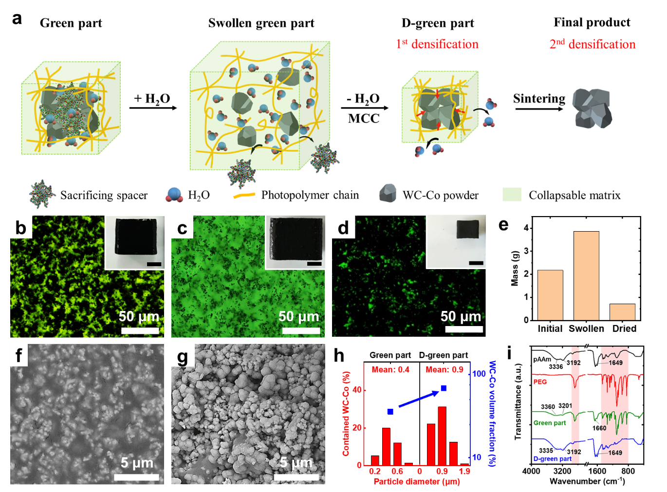
Figure 1 Collapsable matrix assisted printing of WC-Co cermet. a) Scheme of the printing mechanism at molecular level. b–d) Fluorescent microscopic images of the green part, swollen green part and D-green part. Insets: pictures of the corresponding samples. Scale bars: 5 mm. e) Mass of the sample in (b–d) at different stages. f) Representative SEM image of the green part. g) Representative SEM image of the D-green part. h) Measured size distribution and relative content of WC-Co particles in green part and D-green part. i) FT-IR spectrum of various samples. The characteristic peaks of PEG locate at red colored regions.
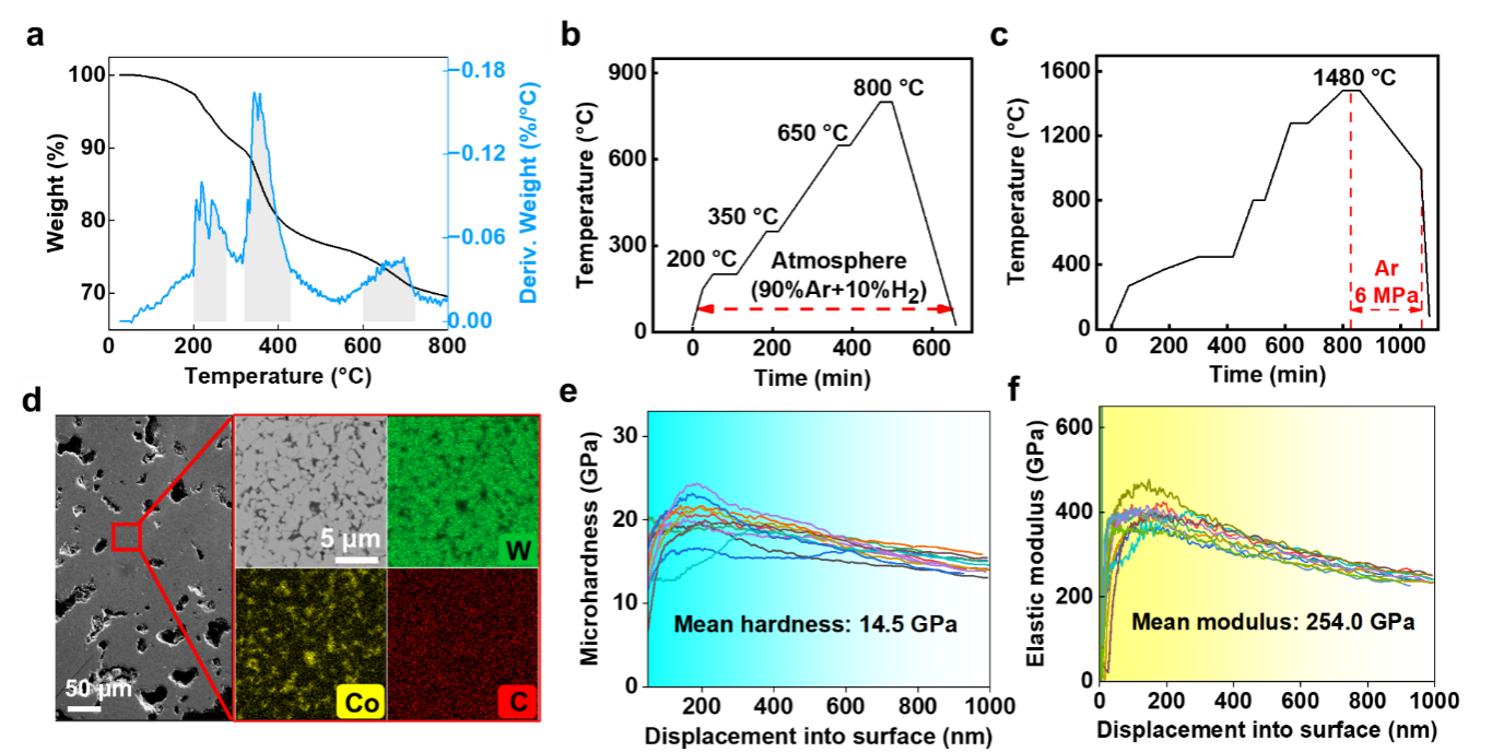
Figure 2 Thermal sintering of printed cermet samples. a) The TG-DTG curves of D-green parts. b) The setup of pre-sintering process. c) The setup of pressure sintering process. d) SEM and EDX characterization of the sintered cermet bulks. e) Microhardness of the sintered cermet bulks. f) The elastic modulus of the sintered cermet bulks.
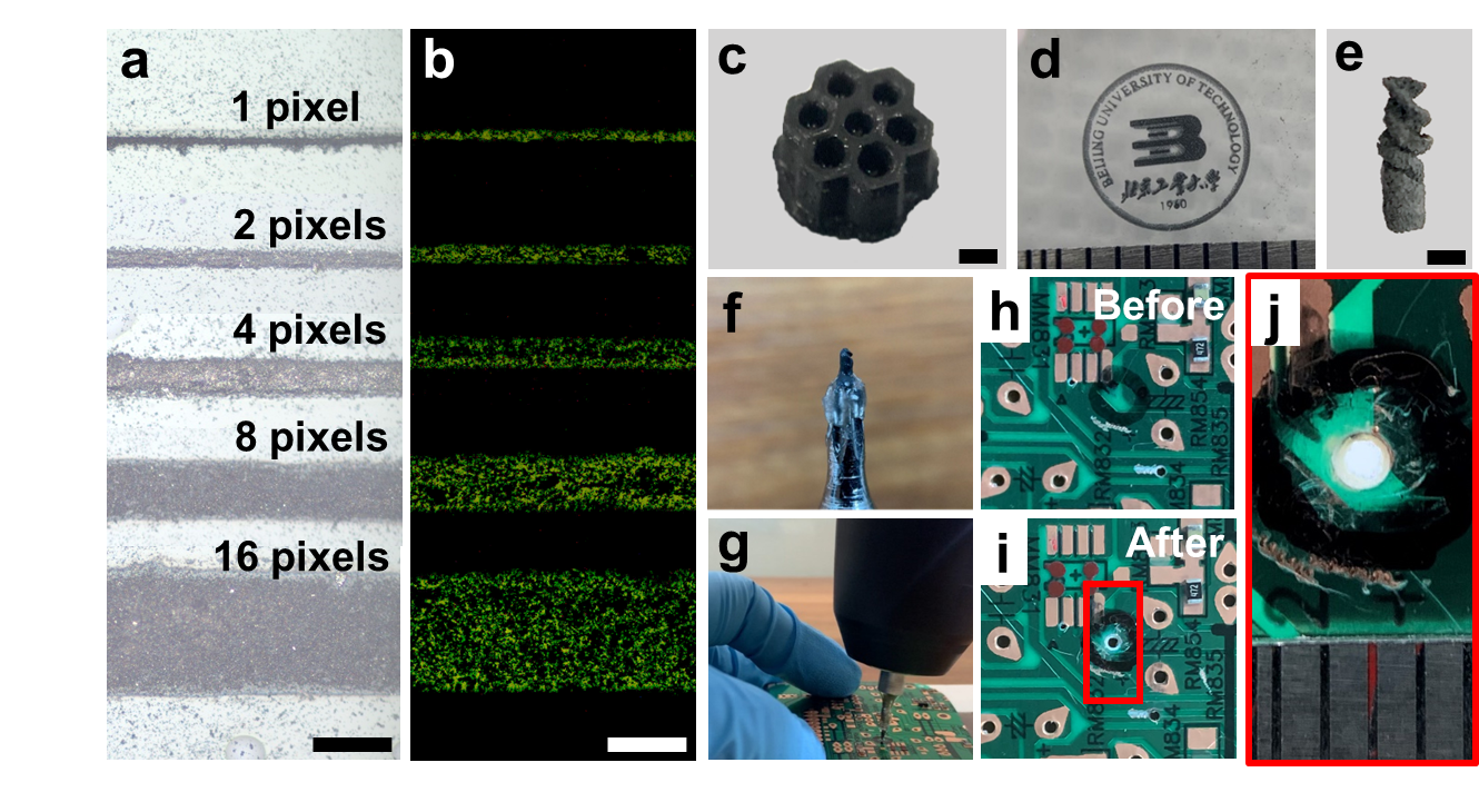
Figure 3 3D printed WC-Co objects and their potential applications. a) Printed WC-Co lines with a designed width of 1–16 pixels. Scale bar: 100 µm. b) Corresponding fluorescent image of patterns in a. Scale bar: 100 µm. c) A freshly-printed honeycomb structure. Scale bar: 1 mm. d) A freshly-printed Beijing University of Technology badge. e) A printed micro-drill after thermal sintering. Scale bar: 1 mm. f) The micro-drill in e) fixed on a hand drill. g) A drill test for the micro-drill in (e). h,i) A PCB board before and after the drill test. j) A magnified image of the red-boxed region in (i).